For general information, see the Microdrive History .
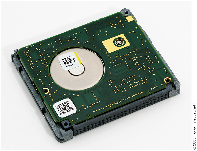
The photos below are test shots from three sessions with a Seagate ST1.1 harddisk. This disk drive is fully CF compatible, and therefore must obey the measurements and extra features of the CF-II form factor, like the connector and the two guiding notches. But you will see that the height of 5.0mm is the biggest challenge...
After removing the label sticker of about 0.10mm thickness, the top foil steel cover of about 0.15mm thickness can be removed. It only protects the main PCB and makes sure that the top surface is smooth. Only the bulge from the spindle motor and the bearing is right below the sticker. You can also see the end of the screw that holds the head stack.
 | |
| Seagate ST1, Top Cover Removed |
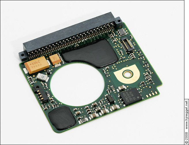
Below you can see the component side of the main PCB measuring 40.0 × 34.3mm². There are three connectors: The 50-pin CF connector has a depth of only 4.2mm, where the four longer pins of the CF host connector are 5mm long. But this saves 0.8mm of precious space. The 20-pin connector at the top right connects to the inner circuit, the 4-pin connector at the left connects to the spindle motor.
 | |
| Seagate ST1, PCB |
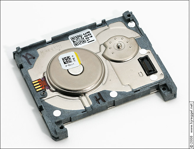
The PCB including all components except the CF connector has a maximum thickness of 2.00mm. After the label and the cover, there would only be 2.75mm left for the chassis and the bottom label. But the components on the main PCB are arranged in such a way that there is less height used where there is a little more height for the chassis needed. The thinnest part of the chassis is 2.60mm, exactly below the large capacitor. Of course, there is an insulation sheet of 0.05mm between PCB and chassis.
 | |
| Seagate ST1, Chassis |
Above you can see three notches where the CF connector would be. This is the space where the four longer pins of the CF host connector go.
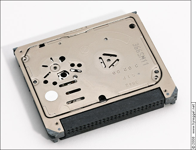
Below is the bottom view of the harddisk. The inside of the harddisk is not sealed with a gasket and a solid plate, instead there is a self-adhesive aluminum foil of about 0.05mm thickness used to seal the chassis.
 | |
| Seagate ST1, Bottom |
Above the triangular arranged cuts, you can see the breather hole. The filter is at the opposite side of the plate, see below. You can also see the magnet of the voice coil motor for the actuator.
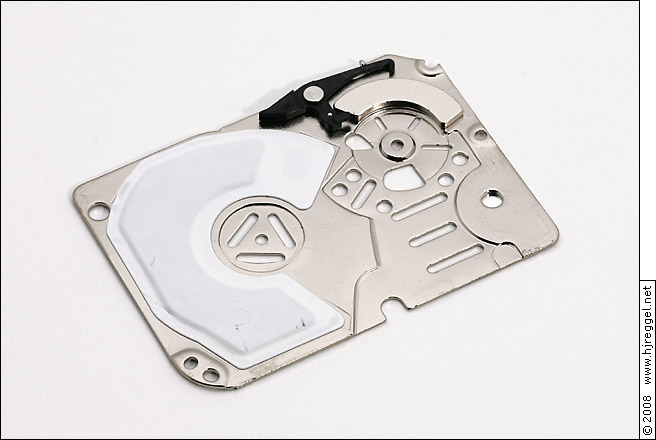 | |
| Seagate ST1, Bottom Plate |
Below is the view of what's inside the chassis. The platter has a diameter of 27.5mm (actually 1.08"), and a thickness of about 0.4mm. At the left you can see the actuator with the head stack. The heads are in the park position on the ramp.
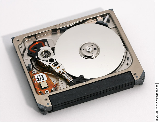 | |
| Seagate ST1, Inside |
At the very left is the circuit with the electronics for the actuator and the heads. This is not a PCB, it's a flex board on a tiny metal plate. At the rear side is the 20-pin connector to the main PCB, and the other end connects directly to the head stack.
Below is a more detailed view of the actuator and the head stack. There are 12 wires connecting to the head stack: 5 for each head and 2 for the actuator. At the right you can see the coil of the actuator.
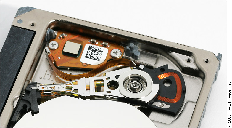 | |
| Seagate ST1, Actuator and Head Stack |
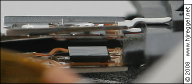 | |
| Seagate ST1, Heads |
Below is one of the heads, the total length is about 21.5mm.
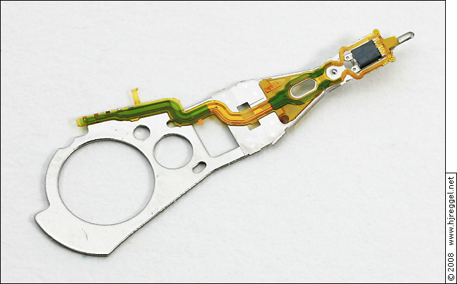 | |
| Seagate ST1, One Head Assembly |
This is a detailed view on the actual head, the size is about 1.05×1.30mm².
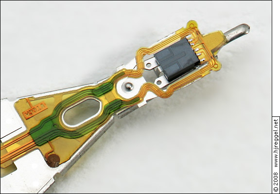 | |
| Seagate ST1, Head |
Below is the empty chassis. The cover plate of the spindle motor is already removed. The end of the flex strip got ripped off while removing the plate. You can see the other end of the flex strip and the purple glue in the chassis view above.
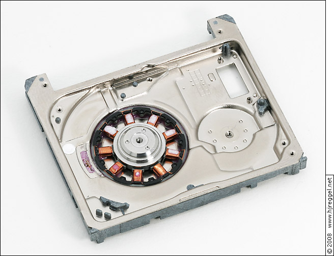 | |
| Seagate ST1, Empty Chassis |
The biggest challenge seems to be the spindle motor. There was a thin metal plate glued on top of the coils, the white residue is from the insulation, the purple residue is the glue. The four connectors got ripped off while removing the cover plate.
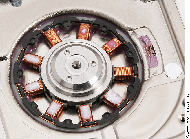 | |
| Seagate ST1, Spindle Motor |
Each of the nine coils is about 1.8mm wide and about 2.5mm long. The wires are about 0.1mm in diameter.